
The instrument cluster on my 2005 Pt Cruiser Limited Edition (2.4L Turbo/Automatic) started cutting out on and off about a year ago. Sometime the cluster works, other times, totally dead, sometimes both (like a wire is loose). This problem does NOT affect starting/running the car at all. It always starts right up and runs like a champ. Related or not, the factory stereo started acting up at the same time. The CD changer cycles endlessly, and lately, the goofy digital volume control it totally whacked, cannot adjust volume down, only HIGH and REALLY HIGH.
The cluster is currently dead. Ran the following tests:
1. Self-Diagnostics Test: FAIL - Cluster is getting NO POWER, so can't run this test.
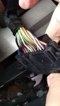
2. Check for ignition voltage at Pin 14 of the 26-way cluster wire harness connector (bottom row, far-right): FAIL - Only getting 0.02 volts. Result is the same whether negative lead on multi-meter is grounded via Pin 1 (GROUND) on the harness plug or grounded to the steel plate behind the cluster.
3. Check for battery voltage at Pin 4 (BATTERY FEED - M1) of the 26-way connector. If no voltage, repair as necessary: PASS - Got 11.42 volts, which is a little low, but assume OK.
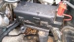
The wire to Pin 4 is tan. Checked the wiring bundle (where visible) for any signs of damage and don't see anything wrong. Squirrels and rats have spent time in the engine bay, but cannot find any chewed wires. I want to pull the Power Distribution Center (PDC) in the engine compartment to check out the connections on the underside, but cannot get the damn thing loose.
Removed all visible bolts (IIRC, there were 3), but it won't budge. The bundle of wires that feed the cluster appears to go into the REALLY BIG bundle of wire that goes into the PDC at some point under the dash, but that's as far as I've been able to get. Suspect corrosion at the connector on PDC, but can't get to it.
Really need to solve this problem fast, as it is preventing me from selling the car to cover bills. Any help much appreciated!
The cluster is currently dead. Ran the following tests:
1. Self-Diagnostics Test: FAIL - Cluster is getting NO POWER, so can't run this test.
2. Check for ignition voltage at Pin 14 of the 26-way cluster wire harness connector (bottom row, far-right): FAIL - Only getting 0.02 volts. Result is the same whether negative lead on multi-meter is grounded via Pin 1 (GROUND) on the harness plug or grounded to the steel plate behind the cluster.
3. Check for battery voltage at Pin 4 (BATTERY FEED - M1) of the 26-way connector. If no voltage, repair as necessary: PASS - Got 11.42 volts, which is a little low, but assume OK.
The wire to Pin 4 is tan. Checked the wiring bundle (where visible) for any signs of damage and don't see anything wrong. Squirrels and rats have spent time in the engine bay, but cannot find any chewed wires. I want to pull the Power Distribution Center (PDC) in the engine compartment to check out the connections on the underside, but cannot get the damn thing loose.
Removed all visible bolts (IIRC, there were 3), but it won't budge. The bundle of wires that feed the cluster appears to go into the REALLY BIG bundle of wire that goes into the PDC at some point under the dash, but that's as far as I've been able to get. Suspect corrosion at the connector on PDC, but can't get to it.
Really need to solve this problem fast, as it is preventing me from selling the car to cover bills. Any help much appreciated!