I have an 05 pt cruiser that shut down while driving and will not crank now unless I jump the connection in the relay port. Starter relay clicks when I test it externally but does nothing when I try to start regularly with relay in place. Anti theft light stays on and is solid. Has check engine light but obd port not working. Does not power on scanner. Also when I tried to jump connection in fuel pump it didn't appear fuel pump was turning on (no sound). I've replaced the actuator pin already. Please help if you can. 🙏

Ksizem1

Ksizem1
Discussion starter
33 posts
·
Joined 2022
- Add to quote Only show this user
I have an 05 pt cruiser that shut down while driving and will not crank now unless I jump the connection in the relay port. Starter relay clicks when I test it externally but does nothing when I try to start regularly with relay in place. Anti theft light stays on and is solid. Has check engine light but obd port not working. Does not power on scanner. Also when I tried to jump connection in fuel pump it didn't appear fuel pump was turning on (no sound). I've replaced the actuator pin already. Please help if you can. 🙏
22,074 posts
·
Joined 2008
Begin at the battery. Terminals can look clean from the outside but unseen corrosion can build up between the post and the terminal:
![Image]()
Wire brush and rinse any corrosion away:
![Image]()
Replace cables if damaged badly from corrosion. Follow to where they attach to the fuse/relay box and to body/engine grounds. Make sure that the terminal connections are clean and tight:
![Image]()
Mice like to build nests and chew wires:
![Image]()
Wire brush and rinse any corrosion away:
Replace cables if damaged badly from corrosion. Follow to where they attach to the fuse/relay box and to body/engine grounds. Make sure that the terminal connections are clean and tight:
Mice like to build nests and chew wires:


5,198 posts
·
Joined 2003
I would agree with your assessment. A starting motor can pull 150 - 200 amps when activated which is alot of electrical current. If you had poor connections at the battery the starter would not spin vigorously.. . . .Also if it was battery cables I feel like it would still not worked when I jumped the pins on the starter relay. That's the only way I can get a crank and it cranks strong. . . .
Two important clues you have given. NO power at pin #16 of the diagnostic OBD II port connector and no power to the fuel pump when you jump the load side contacts of the fuel pump relay. Look at attached image. Note that direct battery power goes through fuse #13 to splice S129 which provides power to load side of ASD relay, load side of fuel pump relay, and Powertrain Control Module and pin #16 of OBD II port. Check splice S129 on underneath side of the PDC.. . . .. Has check engine light but obd port not working. Does not power on scanner. Also when I tried to jump connection in fuel pump it didn't appear fuel pump was turning on (no sound). . . . .

5,198 posts
·
Joined 2003
OK. Check fuse #13 in the PDC. Make sure it has not failed. if fuse #13 good check splice 129 under the PDC box.. . . . .I was not able to jump fuel pump I was only able to jump starter relay. I'm not getting any action from fuel pump. . . . .
22,074 posts
·
Joined 2008
Is there 12v on both sides of the fuel pump fuse?
If the red dot is on in the instrument cluster, it may not start. There should be a fault code stored in the WCM (wireless control module) to explain why the warning light is on. It may not be an OBD2 code and would require a capable scan tool to read.
It sounds like a branch of the electrical system is possibly dead? Flip the PDC over and look for corrosion or broken wires?
Ksizem1
Discussion starter
33 posts
·
Joined 2022
Is there 12v on both sides of the fuel pump fuse?
If the red dot is on in the instrument cluster, it may not start. There should be a fault code stored in the WCM (wireless control module) to explain why the warning light is on. It may not be an OBD2 code and would require a capable scan tool to read.
It sounds like a branch of the electrical system is possibly dead? Flip the PDC over and look for corrosion or broken wires?
Okay I will look at this. Any tips on doing this "The easy way"
22,074 posts
·
Joined 2008
The key-dance doesn't work in all cars. Try the following, watch the odometer display and have a pen & paper ready to write down any codes that appear. Only OBD codes will be displayed.
![Image]()
Ksizem1
Discussion starter
33 posts
·
Joined 2022
The key-dance doesn't work in all cars. Try the following, watch the odometer display and have a pen & paper ready to write down any codes that appear. Only OBD codes will be displayed.
View attachment 85889
So I got codes
Fl0007
Bl 01
Ee 15
Attachments
-
 707.9 KB Views: 294
22,074 posts
·
Joined 2008
I think those are software version and module numbers, not fault codes.
Find a scan tool that can read WCM codes. These are Body codes, not Powertrain
(OBD2) codes.
List of possible WCM codes:
Find a scan tool that can read WCM codes. These are Body codes, not Powertrain
(OBD2) codes.
List of possible WCM codes:
- B1A2A-KEY 1 COMMUNICATION ERROR
- B1A2B-KEY 2 COMMUNICATION ERROR
- B1A2C-KEY 3 COMMUNICATION ERROR
- B1A2D-KEY 4 COMMUNICATION ERROR
- B1A2E-KEY 5 COMMUNICATION ERROR
- B1A2F-KEY 6 COMMUNICATION ERROR
- B1A24-KEY NOT PROGRAMMED
- B1A25-INVALID KEY
- B1A26-MAXIMUM NUMBER OF KEYS PROGRAMMED
- B1A27-SKREEM PROGRAMMING PERFORMANCE
- B1A28-ECM MISMATCH WITH SKIM
- B1A29-SKIM BASESTATION MISMATCH
- B1A30-KEY 7 COMMUNICATION ERROR
- B1A31-KEY 8 COMMUNICATION ERROR
- B1A35-UNIDENTIFIED KEY COMMUNICATION ERROR
- B210A-SYSTEM VOLTAGE LOW
- B210B-SYSTEM VOLTAGE HIGH
- B210D-BATTERY VOLTAGE LOW
- B210E-BATTERY VOLTAGE HIGH
- B2101-IGNITION RUN/START INPUT LOW
- B2102-IGNITION RUN/START INPUT HIGH
- B2204-ECU CONFIGURATION MISMATCH
- B2205-ORIGINAL VIN MISSING/MISMATCH
- B2224-SKREEM INTERNAL
- B2228-SKREEM INTERNAL-RKE RECEIVER
- B2229-SKREEM INTERNAL-SKIM IMMOBILIZER
- U0019-CAN B BUS
22,074 posts
·
Joined 2008
Fuel pump fuse and fuel pump relay.
![Image]()
Should light both sides as the key is turned on for a second and then go out.
![Image]()
Fuel pump relay. Jump #30 to #87 and you should hear the pump run in the back.
![Image]()
Should light both sides as the key is turned on for a second and then go out.
Fuel pump relay. Jump #30 to #87 and you should hear the pump run in the back.
Ksizem1
Discussion starter
33 posts
·
Joined 2022
Fuel pump fuse and fuel pump relay.
View attachment 85907
Should light both sides as the key is turned on for a second and then go out.
View attachment 85909
Fuel pump relay. Jump #30 to #87 and you should hear the pump run in the back.
View attachment 85910
This does nothing

5,198 posts
·
Joined 2003
I do not mean to offend anyone who has offered solutions and diagrams for remediation. But you need to determine if there is 12 volt power going through fuse #13 in the PDC and through the splice 129 and onto pin #16 at the diagnostic link connector. If there is no power going through that splice 129. no power to control side of ASD relay, no power to load side of fuel pump relay, and no constant power to volatile memory in PCM and no constant power to diagnostic link connector.. . . . I read a thread of someone who has the same problems as me down to the t. Even no power to obd and it was an open circuit from ignition to pcm anyone know how I test this. I have a multimeter. . . .
22,074 posts
·
Joined 2008
I think he means C3 (3rd from the left), there is no C8 on the PCM.
Pin #38 is the Tn wire from the starter relay. Grounding this wire should crank the engine.
![Image]()
Pin #38 is the Tn wire from the starter relay. Grounding this wire should crank the engine.
5,198 posts
·
Joined 2003
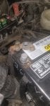
See attached image. Open the wire splice with the RD / WT wires. At least one should have battery voltage. This splice connnection looks like it has glue that is attepting to seal the joint connection from corrosion. I wonder if glue has melted and is now forming an electrical insulator between the individual RD / WT wires?. . . . Checked 129 at the splice. .9v . . .
Also check the mating socket at the fuse box where the blade of fuse #13 attaches. That must be secure and tigjht fitting.

384 posts
·
Joined 2021
Factry splice or not I would say that that splice has issues. Along with what looks like a brown wire next to it. There are 5 wires in that splice which agrees with the wire diagram. I believe what allenc is saying is that if you separate the spliced wires one should certainly have 12v on it. That should be the wire from fuse 13 provided fuse 13 is good & the output connection wire is good to the splice. Since you are already there it seems that verifying that the wires out to the relays/OBD pin 16 are good & then resplice those 5 wires.
I’ve seen weirder things. Chased a open wire once that had just been reterminated at a switch. The wire looked good at the termination but upon further inspection, the strippers used had only removed the outer wire cover & not the mylar/kapton inner coating which has a coppery color. The wire itself was actually silver coated copper & the tech that crimped the terminal did not realize that.
What a headache. I hope my 05 P GT doesn’t develop this kind of issue & I hope this is a fix.

384 posts
·
Joined 2021
Just tossing this out there. Try testing with a test light or some type of load. A 12v bulb will show a poor connection or high resistance connection much better than a meter, especially a digital meter. Or you can try reading voltage drop across connections to get the same thing. 1 strand of a wire will show voltage but will only dimly light a test light usually. I am with AllenC in that it appears to be a amp draw problem that pulls the voltage down across a connection someplace.
384 posts
·
Joined 2021
One check you can do is pull fuse 13 & reattach the pos cable. Then read volts from the center of the top of batt pos post to batt grd post & then read from the fuse 13 input side to batt grd post. Should be little if any diff In volts. If there is then that is a poor connection between pos batt & the PDC fuse 13 input side like AllenC said. I think that is the right track. Don’t forget that brown wire. It needs spliced back together.
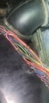
I have to correct myself. 6wires at that splice 129. From your last pic it looks like the 2 wires still in the splice must go to PCM & OBD. You can do a continuity check of those, unplug C1 @ PCM & check between splice & pin 29. Then between splice & OBD pin 16. The 3wires going north in the pic look to go the ASD & fuel pump relays respectively. The 4th wire to fuse 13. At least from the pics & the PDC lid.
You can make a test lite from a bulb & wire in a pinch. 😉
Good luck! & if you have any fixes for why revs would hang when shifting let me know!
Ksizem1
Discussion starter
33 posts
·
Joined 2022
Pt is running problem solved. Splice 129 had no power redid splice spliced other damaged wires under PDC as well put a new fuse is #13 and she is good to go!!!! THANK YOU TO THE MEN WHO HELPED ME!!!! IF YOUR EVER IN MAYFIELD KY NEXT ROUND IS ON ME!!!!
THANKS AGAIN
KEITH
THANKS AGAIN
KEITH
5,198 posts
·
Joined 2003
Glad you got the problem solved and engine that will now run. Posting successful results helps everyone learn about diagnosis.. . . Pt is running problem solved. Splice 129 had no power redid splice spliced other damaged wires under PDC as well put a new fuse is #13 and she is good to go!!!! THANK YOU TO THE MEN WHO HELPED ME!!!! IF YOUR EVER IN MAYFIELD KY NEXT ROUND IS ON ME!!!! . . . .


-
?
-
?
-
?
-
?
-
?
-
?
-
?
-
?
-
?
-
?
-
?
-
?
-
?
-
?
-
?
-
?
-
?
-
?
-
?
-
?
- posts
- 836K
- members
- 60K
- Since
- 2002
A forum community dedicated to Dodge, Jeep, Ram, Chrysler, AMC owners and enthusiasts. Come join the discussion about performance, modifications, classifieds, troubleshooting, maintenance, and more!